I've also seen a page (looking for it again) where somebody hacked up the cheap 2 for $30 FRS radios.
Charles (http://www.texnet.net/ccent/rockets/txrx/tx433%20transmitter%20construction.htm) has a nice battery time curve too, showing a 9V should last a week on this setup, and also confirming my theory that the tiny 12V batteries are barely good for a day.
I built RDF TX & RX circuits based on Pete's designs but need to work up a page detailing that work. I tested them at the July Whitakers launch in my PML Bullpuppy 2.1. Then folks left cleared out when a small shower rolled in so after that cleared I tossed the TX into various places, like a corn field, then one end of the pasture, etc, and determined my working ranges through corn (1/2 mile max), pasture (3/4 mile), and open ground (about 1 mile).
Continuing on this (fodder for a real page) I'll detail the flight report for that BullPuppy. I flew it on an AT F20-7 for an estimated 1000 ft flight (maybe a little more). Straight up and nearly straight down. I then "forgot" where the rocket was and used the RDF to find her (only 100 yards away max). As I got close, the RX was overloaded and I started losing directionality on the yagi. Using body shileding, I still got a reading straight ahead. But wait! Over to the right was, what?, my rocket! With no RDF TX. But the RDF RX Ant was pointing ahead. I had to clear and wait for another relay of rockets and then found the TX, by itself, with the end cap popped off, merrily beeping away.
Looking further I saw that the kevelar thread (about like carpet thread) was cut. Looking on the rocket I saw a nick in the top of the ejection piston. The kevlar thread had been cut, at apogee, and the TX had come in by itself, ballistic, from apogee and survived! That is rugged! I did replace the kevlar with heavier cord (Pratt "small"), longer, and with looping to prevent losing the end cap and to keep it together. I also tape the battery in again.
Now, I drop that TX in almost any flight at all. For the close ones, I'll leave the RX in the truck in case I really need it, and for the high ones I'll go ahead and bring it to the pads to get a bearing on it as the rocket descends.
I am very happy with this project. And while not having the same range as the popular Walston RDF it is very workable. Sheesh. You know, I really think I have a hacked up page on this somewhere ... but until then, here are a couple of pictures:
This is the completed TX, RX, ready to use. I do now have a neck strap on the RX box.
This is an internal view of the TX and RX. Note the TX is deadbug on the back of a N battery holder. The antenna is RG-174 coax and it's strain relief'd by being gobbed on with E6000 glue.
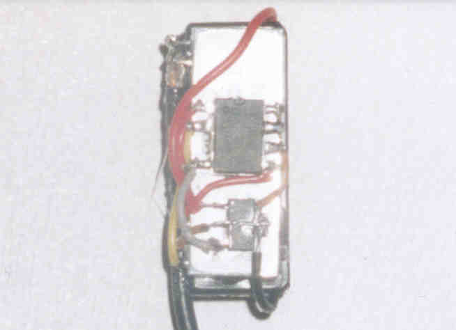
Deadbug construction closeup. Note the PIC (in the middle) is hot glued onto the Radiometrix TX. The 3V 90ma regulator is to the right. The Radiomextrix nearly perfectly matches the size of the N battery holder. With the regulator I can run anything from a 3V to a 12 V battery in the N holder. The 12V and 6V camera batteries are the best candidates with 6V the best.
Voltage Regulators
I prefer low quiescent current / low dropout voltage regulators. The low quiescent current may not be a factor since I'm don't think the PIC idles at low enough current to let the regulator go quiescent - but these regulators also seem to be more efficient in their internal current needs and I like that. This class of regulator is specifically designed for battery operated devices. Every mah saved is more time to find a rocket. The low dropout also helps as it provides both stable power to the output down to a much lower supply voltage. The voltage delta also seems to be much lower. Getting a decent regulator with these characteristics, such as a LP2950 costs about 0.80 whereas a generic LM78L05 is about 0.26. Myself, I'll drop the 0.50 extra. These are the 100ma parts.As an example, a generic LM78L05 may require as much as 7.7V input to reliably provide 5V output, whereas a low dropout may require as low as 6V to reliably provide 6V output. That can make a difference if your rocket is lost and you're on day 3 of searching. It also provides longer overall service life of a battery if you're not losing your rockets for long.
Note that these regulators, particularly the 100ma and smaller, really do need input bypassing and output bypassing is also suggested. A 100nf ceramic on the input is usually recommended, and a 1uF to 10uF on the output is also nice. A larger output value helps some too if your regulator shutsdown and motorboats and might help keep this from happening. For bypassing, when building ugly bug, I usually use the ground pin of the PIC as the solder anchor for both the input and output capacitors for the voltage regulator (and the Vcc pin of the PIC as the other output cap pin). This is just a deadbug mechanical arrangement. Note the above picture doesn't have the bypassing. It seems to work fine, but I now use the bypassing.
I've used both the 100ma parts and also the even lower power parts - some as low as 40ma. The 40ma parts will power the PIC and a TX with no room to spare but will perform that reliably. The 90-100ma parts aren't required unless you're also going to be powering a piezo or other circuitry - and then usually only if the piezo will be powered at the same time as the tx (hint, modify the pic code to use a separate pin for piezo and to direct every third beep to the piezo instead of the transmitter and remain at the lower power budget).
When purchasing, also be aware of the packaging. I didn't once, and ended up with ultra tiny SOT-23 packages which make wire wrap wire look like a high current bus bar. They are almost an inhalation hazard and carpets are very hungry for these! The SOT-223 are a bit more workable - you can at least hot glue them easily onto your TX and then solder the fine wires. The above pictrure shows SOT-223 packaging - and a SOT-23 will entirely fit inside the black area of the SOT-223. I prefer the TO-92 packages as they're even easier to work with. But note the 100ma devices are probably the lowest current you'll get in TO-92 packages (and you can get 90-100ma in SOT-223).
Battery Choices
The above uses a miniature 12v battery in an N cell holder. It's compact and works fine - but has it's issues. The battery doesn't last long for one, and it's inefficient due to the high delta voltage to our PIC/TX needs. They're good for about a day's (or launch weekend's) use.Next prefereable would be one of the 6V camera batteries in a 1/2 AA or similar size (there is a slightly larger size I don't know what it is). These are excellent for power capacity and life. They are more expensive as a downside. Another advantage is if you use a silicon diode in series instead of a regulator, you'll have 6V - 0.7dv == 5.3V which the PIC is happy with - eliminating a voltage regulator. If you use a regulator (esp with the 3.3V Radiometrix parts) you may want to ensure you use a low dropout regulator to have a tighter voltage.
Since I fly mostly high power, and room is not an issue, I've switched almost exclusively to 9V radio batteries. The're commodity items so cost is relatively cheap and they can be had in high capacity version if desired. Charles Barnett found useful life up to a week (though with reduced output) in his RDF applications.
Battery Holders
Always use a very secure battery holder with good end bracing. And always secure the battery - you don't want it popping out!PIC Code Modifications
I'm considering modifying the timing of the PIC to have- a shorter interval between beeps. Perhaps I'm over-anxious when sweeping, but a shorter interval, even with shorter beeps, is my current desire.
- lowering the settling time of the transmitter when powering up could be shortened as it appears extremely generous given the current specs of the TX-2 transmitters.
- drive a low current piezo, perhaps on a periodic interval. This would help finding it when you're close or getting close.
- have a conservation mode, where the PIC goes into very conservative timings after, say, 3 hours, figuring at that point a quick recovery is not in order and the TX needs to conserve battery for what is likley an overnight (or worse) longer recovery duration.
TX/RX/RDF Resources
Charles Barnett's RDF work http://www.texnet.net/ccent/rockets/txrx/TXRX%20information.htm he's got a line on, in particular new RX that may be better and may also be making some PCBs. check it out. The Rocketry Online Electronics forum is also a good forum for information, questions, and answers. Dave Muesing started a good RDF / Radiometrix thread on that forum.The TX2 / RX2 Data Sheet
Programming & Customizing PICmicro Microcontrollers is a great book.
Build Your Own Low-Power Transmitters : Projects for the Electronics Experimenter looks interesting
Here's Joe, WB2HOL's good RDF Project page (tape measure, PL-259 attenuator, TDOA).
Attenuation / Attenuators
The yagi antenna described gives me about a mile of range, yet when within even 50 yards, it's nearly omnidirectional. Techniques such as antanna tilting, off axis rotation, etc, can help, but an attenuator is desired to just "flip in" some or a range of attenuation to allow the antenna to be used to a much closer range. At some point, it's still down to no antenna and body shielding (say, when in the corn).I haven't built one yet, but googling ham radio RDF links come up with some nice inexpensive solutions.
A bnc / PL-259 based attenuator. Simple. http://home.att.net/~jleggio/projects/rdf/p_atten.htm
A rotary switch variant of a resistive attenuator http://www.siteswithstyle.com/VoltSecond/12_posistion_shunt/12_Position_Pure_Shunt.html
A pi network resistive attenuator (as the arrow antennas kit is baed) http://www.merseyworld.com/wadarc/Attenuator/Attenuator.htm
A relatively inexpensive kit Dave Muesing dug up. http://www.arrowantennas.com/atten.html
A potentiometer simple attenuator http://members.aol.com/bmgenginc/PotAttn.html
On attenuation, I had another thought of folding back the active elements, say if you had 6 directors, you would fold 3 back on themselves.i.e. the boom folded back. I don't know if the reduction would be significant or not. I suppose one could also have folding elements Similar to the Walston, and just fold back the elements or arms so they were effectively out of circuit (though I'd worry about side signal confusion).
Gain / Pre-amps / Antenna
mods.
I find that the Radiometrix TX / RX pair has acceptable performance,
but I would really like more gain. The Walston has such further range
and the TX is much lower power. That tells me that I need more RX
performance. RX performance is antenna and receiver.Pre-amps
I think the Radiometrix RX is likely not tuned to high sensitivity
figures. I should look them up and compare them to an HT and /or
scanners. But I am thinking a pre-amp would help a lot.Here is one inexpensive 440 mhz kit: http://www.hobbytron.com/R-PR-40.html Perhaps one could build that into this kit http://www.arrowantennas.com/atten.html replacing one of the attenuation stages (for compactness)
Antenna
The Pete's Yagi seems roughly comparable to the Walston. I haven't done
the math, but if anything the Pete's has more gain. So from that
perspective I guess I'm not thinking of adding more elements. Though
it's compact enough I could probably add 2 or 3 more and still have a
reasonable sized antenna.I am also investigating a loop antenna, much as http://www.arrowantennas.com/fhl.html to build. The null is very sharp, but it's an intermediate solution - it doesn't have the gain of a yagi - but may still require attenuation at some point. But the sharp null is very attractive. Perhaps using the yagi to get close and then finishing the job with attenuation and loop? something to ponder.
Tape measure spring steel for elements - advantages are durable in the woods and the box. Might not be rigid enough for poking out the truck window while driving. The dimensions aren't for this 432 mhz, but I like the idea and was thinking I'd use the tiny tape measures for narrow spring steel (3/16" or so)
High Gain Quagi
Loop Antenna Resources (one hit) look for addl links at the bottom. The loops seems nice due to the sharp null, but I am finding essentially no untuned loop projects; all seem tuned. I am thinking that Arrow Antennas may perhaps be resistively swamping their loop to de-tune it. If that's the case then that'd be easy. That would fit with some reviews liking the antenna but stating that it is rather "deaf". I suppose I could also take a shot at resonating one, but that is so sensitive (due to small size) that it may (?) be better to swamp it resistively. Esp since I don't have a grid dip meter or other equipment to resonate one.
TDOA RDF Aid
A TDOA may be as inexpensive as a loop, and the gain wouldn't be as down as the loop. Not sure about the sharpness of the NULL.Quoting: from one nice page for a $10 TDOA unit: "
The TDOA works by detecting the difference in the phase of the RF signal received by each dipole. If both dipoles are exactly the same distance from the RF source (the "fox"), the phase of the RF signal will be the same at each antenna. If you rotate the array, or the RF source moves to the left or right, then one dipole will be closer to the source than the other one, causing a small phase difference between the signals received. Your FM receiver will then detect an abrupt change in the phase of the RF signal it receives as the antenna switching unit switches rapidly back and forth between the two dipoles. To the receiver, the signal looks like square-wave- modulated FM ! Your receiver's speaker will emit an audio tone at the antenna-switching frequency. As the phase difference increases, the tone becomes louder. When both dipoles are equidistant from the source, the tone almost completely disappears.
One disadvantage of the TDOA is that when you have found the
"null" or antenna position where the tone disappears, you cannot tell
if the source is directly in front of you or directly behind you.
Fortunately, there are other ways to determine this. A quick way, if
you are using a handheld, is to use the "body shield" method -
disconnect the antenna, hold the handheld close to your chest so that
you can see the signal strength indicator, and turn your body. When the
indicated signal strength is minimum, the source is somewhere behind
you. Another technique involves converting the TDOA antenna to one
which has a cardioid or heart-shaped radiation pattern - the null
(which corresponds to the "notch" in the heart-shape) can be used to
point a rough bearing to the source."
http://webhome.idirect.com/~griffith/tdoa.htm
Joe Leggio WB2HOL, has a couple nice TDOA units on his RDF Page.
http://home.att.net/%7Ejleggio/projects/rdf/tdoa2.htm
http://home.att.net/%7Ejleggio/projects/rdf/tdoa1.htm