Hybrid Ground Support Equipment

HyperTEK and other launch controllers

This section is a mess, but down lower I have pin outs, schematics of HyperTEK boxes, and also a nice schematic of a simple fill/fire relay launch controller.
Solenoid Saver, HyperTEK GSE Pinouts & Schematics, Simple Relay Launch Controller (high res and low res)

Home Brew 12V multi-pad launch controller

Here's a bunch on my over the top homebrew launch controller & hybrid GSE. You may want to build a simpler version as described below.

Pictures

Here are some pictures of the GSE I built. I need pictures scanned of the gas solenoids but do here have pictures of the relay boxes. They are shown connected with a short test cable. In practice a 125 ft long CAT5 cable connects them.y

The yellow box is normally entirely powered by the orange pad box. The CAT 5 cable carries only low current relay control signals (though for an instant, upwards of an amp can be flowing depending on the number of lights and relays being controlled or signalled.


RSC & LSO Boxes
Yellow LCO controller and it's companion pad slave relay box.

RSO & LSO box inside out
Inside detail of both boxes. Note that the relay panel on the pad box is not the final version. It turned out that the surplus relays were defective. I also wasn't happy with the mounting of the continuity relays (seen in the upper right in orange) as that seemed particularly weak.

LCO Box - insides as built
Here's the as-built detail of the pad box showing the final configuration of the relay board.  Note that I switched to using only 3 headlight relays - those for the igniter relays, and used somewhat more compact relays for the gas solenoids (shown on the PCB). I also chose PCB mounted DIP relays for continuity detection and PCB mounted these as well. I'm much happier with the strength and integrity of this relay installation than with the previous version (defective relays aside).

QA team at work
Here's my quality assurance team at work. If anything is under designed or under built - they will flush it out.

Label artwork application
Here's the LCO panel with the artwork label applied and awaiting final trimming. Note the sharp knifes for trimming and the rubber roller to ensure good adhesion. The artwork was done up in layers in PaintShop Pro and printed to Avery single sheet label stock (yes, a single 8.5x11 sheet of unbroken label) from the office supply store.

I prefer laser printing to ink jets for artwork such as this - it's simply more durable and not prone to bleeding. Even still, I shot the label with several coats of Krylon clear to seal the printing and the label from abrasion as well as the label, making a fairly durable product.

Label artwork how to cut
Here's a nice shot of both panels trimmed and ready for parts installation. Do always use a fresh X-Acto blade and do change it out if it's not cutting cleanly or is starting to tear. Trimming tight against punched & drilled AL can quickly dull knife blades. Don't be cheap!

Solenoid Saver

I used regular N2O speedshop solenoids. As such I'm at risk of them burning up during extended fills. Top that off with a very hungry current draw and you'll kill your battery.

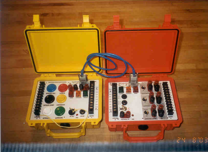
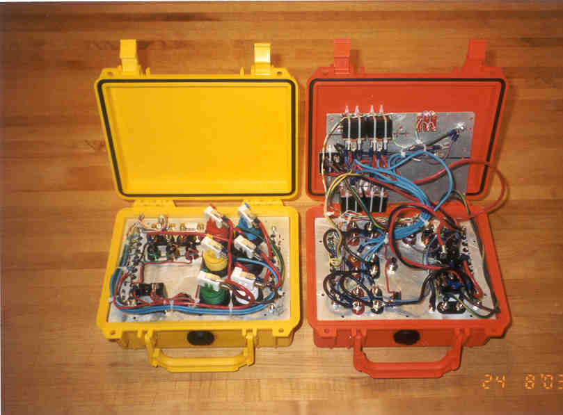
I build a Solenoid Saver along the lines of the one described at the NowHybrids Solenoid Saver page.  Here's a picture.

solenoid saver picture

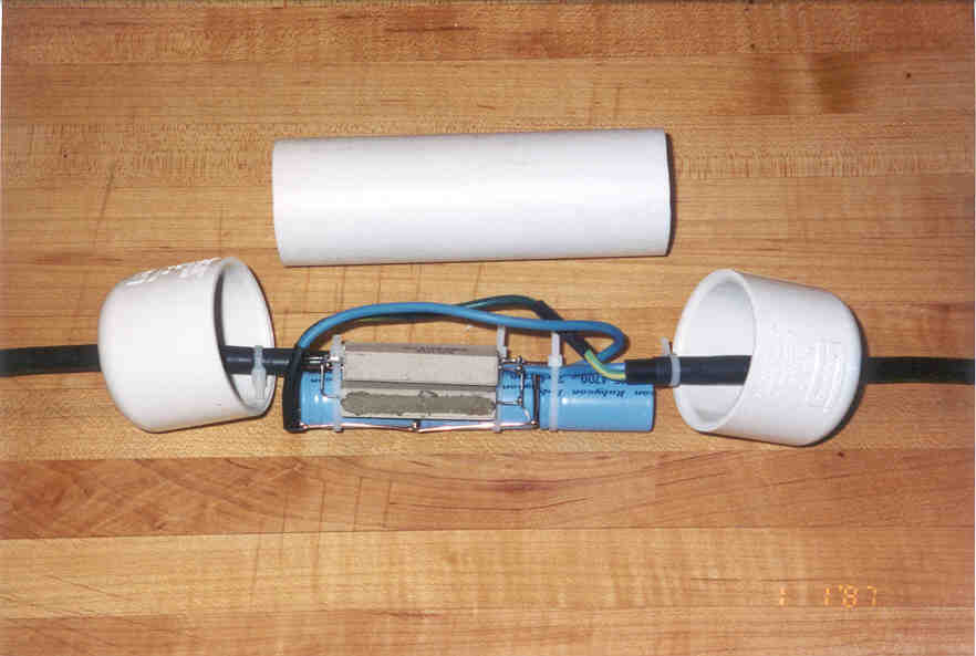
This picture is as it was built. I've since had to augment the components.

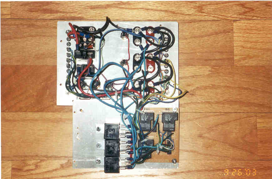
As built, it had 3 capacitors of 4300 uF at 25 V each in parallel with 3 power resistors of  33 ohms. I found it worked reliably at lower temperatures (below 70F) but was intermittent in the 70-80F weather and wouldn't open at 85F with the N2O at 910 PSI. That's about max pressure for flight so I wanted reliable operation at that pressure.

I cobbled up 3 2200 uF caps out of a PC power supply and also added my last 33 ohm power resistor. Some how the additional parts still fit in the tube above, tight as it now is. These should give a longer open surge with a slightly higher hold current.And to not be fighting my GSE on the field again,  I tested this on a hot day on my driveway. It worked reliably at 910 PSI if not perhaps having a single pfft to vent perhaps higher pressure in the solenoid area.

Previously it wasn't hot enough to test, not even in the house, without perhaps a hot shower :| . if possible I recommend (1) testing your solenoid saver at pressure, through whatever means necessary, and (2) bringing an alligator clip to short it out, something I've done with igniter wire in the past.

If you do test, you'll find it reliable. Just test it to ensure the components are right for your solenoids. My Fill solenoid is a monster solenoid from N2Operformance.com and is current hungry. (I'd already learned it wouldn't open on a pad battery that had dropped a cell). I needed a meter for that (as rockets were otherwise launching and my dump solenoid worked). Bring a meter.

I did do one unique thing. You could call it cheap too. I ran a 3 wire to the solenoids and installed the solenoid saver in the return / ground lead. This way it works for both fill and vent solenoids. The only issue is ensuring it's plugged in correctly. I did this wrong once and it (1) acted funny, and (2) didn't work, and almost scrubbed a day of launching. So if you do this, wire it in permanently, or at least mark your connectors and polarities well.

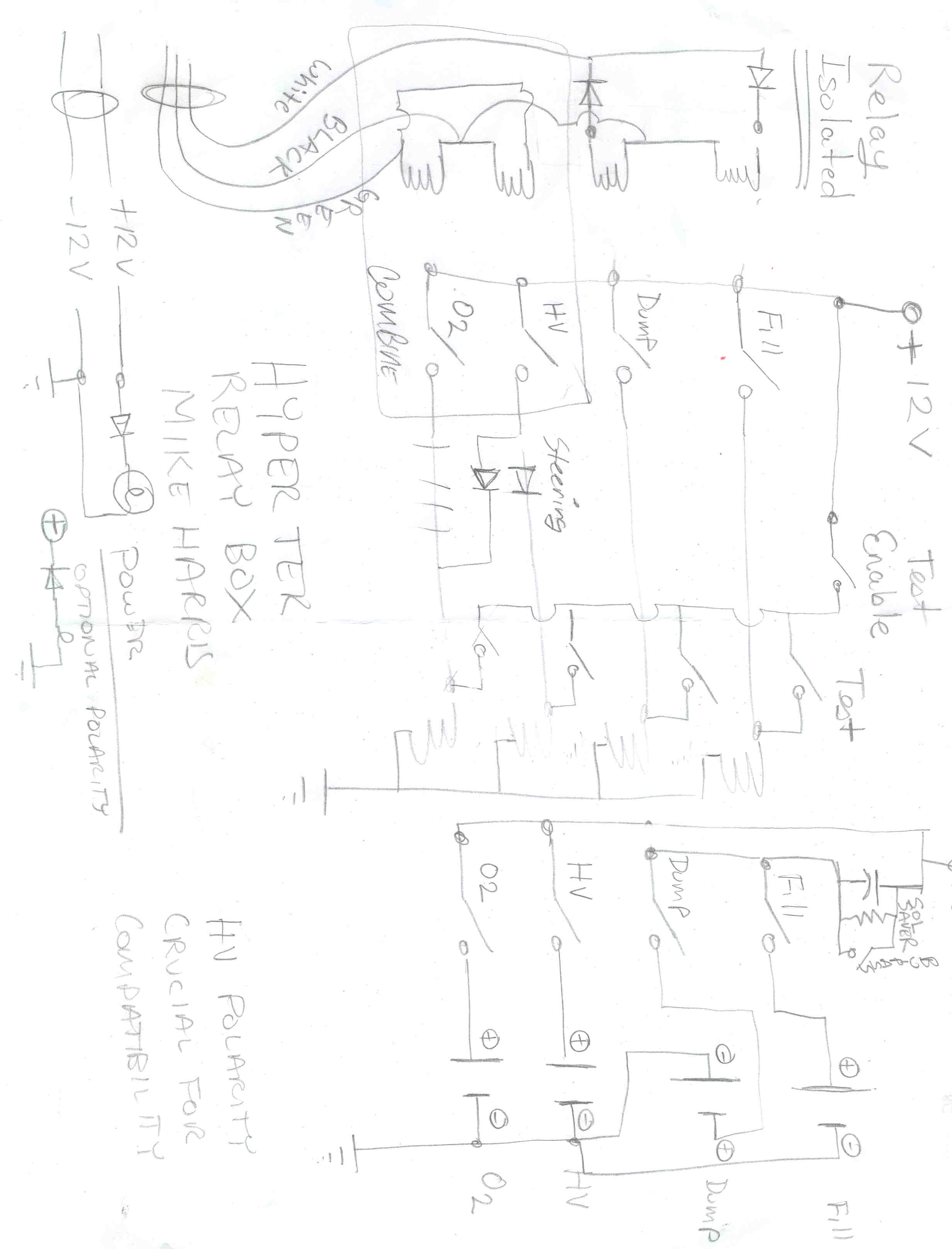
I also have a schematic of the HyperTEK Solenoid Saver circuit as built in. Note that we got this on Beta and replacement equipment, but it doesn't seem to be standard anymore. Note also that had to up the Capacitance to 20,000uF to get reliable fill solenoid operation under higher N2O pressures.

Hack paste of e-mail on Solenoid Savers from Hybrid Rocket Motor Yahoo group:


At 04:17 PM 12/19/2004, you wrote:
>A could do with a little help on this one not least because I am not too hot
>on electrical stuff. Not hot at all.

Ref: Now Hybrids link: http://www.nowhybrids.com/solsaver.html


>1) In the Now Hybrids schematic it shows a capacitor of 11,000 uFDs (I
>assume these are micro Farads). Can I confirm that this is correct - it
>appears to be quite a large capacitor.

Yes, that is 11,000 micro Farads.

>2) Assuming it is correct....Mike Harris suggested doubling the capacitance.

Mike here. yes, I added about 50% to my capacitance.

Ref: My link: http://www.privatedata.com/byb/rocketry/hybrid_gse/index.html

but (a) I have  a monster solenoid that wouldn't always open, and (2) I
filled the available space with the extra capacitors - I didn't add one and
test and decide to add the other. I just put two more in because I had them
and they fit.

My monster solenoid is one of the biggest that ColdFusionN2O.com had (was
an eBay item). It is high flow, but is an absolute current pig. In fact, it
won't operate if a battery has dropped a cell, where most will work well
below that voltage. I also added another parallel resistor to give an even
higher sustain current, as mine often would click but not hold. So  my mods
must be taken with that in mind. That said, going heavy on the C and light
on the R won't hurt. Mostly, test at max pressure for reliable operation.

>The capacitor I have sourced at my online store quotes:
>
>22,000uF
>rated at 16V
>max current 21A
>(very surprised how expensive they are - £11.92, circa $23)

Very expensive! I sourced most of mine out of old computer power supplies -
a very rich source of high power components. And with capacitors in
parallel the values don't have to be the same, just keep paralleling them.


>3) The resistors........The text is not totally clear - my reading of it is
>42 ohm, 25 watt. Is this correct? If so would I be looking at getting a
>wirewound resistor here?

Any power resistor will do with a requisite power rating. So here, you're
looking at 22 ohms 50 watts

For most solenoids, it's not too critical.

Now Hybrids Page: 11,000 uF for C and 22 ohms at 50 watts.
My Page with monster solenoid caveats: 1650 uF for C and about 8.5 ohms.

I was disassembling a HyperTEK pad box and it had a solenoid saver in it. I
was from Doug Pratt, but I don't think he added the saver circuit. Given that:

HyperTEK Fill: 10,000 uF for C and 16 ohm for R
HyperTEK Dump: 10,000 uF for C and 35 ohm for R

[mikeh - note 4/2005, the 10,000uF on the HyperTEK Fill was not adequate to actuate our old / large / NOS Fill solenoid, so I had to short it out. I am planning on upping the Capacitance to 20,000 uF as is on mine. Maybe also provide a bypass switch for those bad gass days.]

Do note that I put my solenoid save in the "common return" leg of a 3 wire
cable going to the solenoids so one saver circuit serves both fill and
dump. This works great as long as you get the polarities right when
plugging into the GSE. Mine terminate in two two wire banana jacks and I
plugged them in wrong one day and Doug and I had no end of trouble with
that. -Remember the capacitors are polarized and it *does* matter. Built
into the pad box like HT there's never an issue, but they do use two
circuits, and you'd have to add, I think, a diode to have one do both on
HyperTEK's box due to the diode switching.

Chris Eilbeck mentioned PWM and I think Now and Pratt both have these
modules available. Or maybe Now has the PWM and Pratt has the O2 sequencer?
Hmm...

So I recommend scrapping computer power supplies for your parts, and that
the nominal values should be just fine as long as you don't have the odd
pig of a solenoid like I do.

regards, Mike

Pratt

Reccommend Doug Pratt's BFV fill solenoid if not his other solenoids - low current special wound solenoids that don't need the saver.


HyperTEK GSE Refurbishement

I've discovered our Whitakers Club HyperTEK GSE is Beta equipment from Korey Kline. I did a little re-work. I'll post more details, but here's a picture for now:

HyperTEK GSE Refurbishment

Whitakers HyperTEK / Hybrid Relay Box

I built a relay box for the Whitakers Club.

All functions on on 30 A DC headlight relays. 10 A Ampmeter, Solenoid Saver & Solenoid Saver Bypass :), and "at the pad" test buttons (two button sequence) for each function separately (including O2 separate from HV/DC). No more hollering to LCO to give an O2 test. Also relay lights for relay engagement.

Custom HyperTEK GSE Pad Relay Box

I also decided to add an at-the-pad igniter continuity test button, so I will add that when the parts come in (mostly matching pushbutton switch - I'm so vain).

Click Here for the Schematic.

N2O Nitrous Solenoids

I highly recommend the Solenoids that Doug Pratt sells. They don't require a Solenoid Saver Circuit. But if you want to roll your own, you can find them on eBay. I, myself, found great deals from Mike Ware at http://www.coldfusionn2o.com . Ask him for his eBay / Internet / Rocket pricing . I got a good deal on a 15lb tank and also a monster solenoid from him.

My dump solenoid is a used NOS "Cheater" solenoid off eBay. More money is better spent on larger fill solenoids!

My Fill solenoid is a Cold Fusion N2O (Nitrous Warehouse) #1803 / SUPERMAX N2O solenoid. I'm told it has a 0.125 orifice, which, according to the information on the  products page at West Coast Hybrids, should be good for a 2 minute M fill.  Note that this solenoid requires 20,000uF for the solenoid saver, and also won't work if the battery drops a cell. It's hungry.

Quick Disconnect Couplers

I used the following quick disconnect coupler styles for the Whitakers Hybrid GSE. I'll be brief as the main intent is for reference on the type / model to ensure future compatability when ordering.

http://www.mcmaster.com parts 6543K43, 6543K33, 6537K53 or the catalog page http://www.mcmaster.com/ctlg/DisplCtlgPage.asp?reqtyp=catalog&CtlgPgNbr=242

Plumbing Parts (collect all right now)

The Nickel-Brass Instant Tube Fitting / Push To Connect
McMaster Nickel-Plated Brass Instant Tube Fittings Page


1/8" McMaster
1/4" McMaster
1/8"
51495K181 51495K187
5/32"
51495K182 51495K188
3/16"
51495K183 51495K189
1/4"
51495K184 51495K191
5/16"
51495K192
51495K185
3/8"
 51495K186 51495K193


West Coast Hybrids uses the McMaster Carr PN is 5779K105 for a LP PTC

Brass Check Valve for backlash in the O2 line 7768K15 (low pressure)
Brass Check Valve for N2O line 46105K61 (high pressure)


AN / JIC 37 Degree Sealing Surface Compatability

From http://www.batinc.net/files/ahosend.pdf     :

AN (Air Force/Navy) specification hose and fittings refer to "dash" sizes, arrived at by multiplying the nominal bore size of the hose by 16, hence 1/2" hose equals -8 [ and 1/4" equals -4AN ]. The hose end fittings we list are designed to be used with Aeroquip FC333, or similar specification hose. Hose end fittings seal on a SAE 37 degree flair making them compatible with other components that share the industry standard AN / JIC 37 degree sealing surface.

This is great news as we can now map the AN fitting sizes to 37 degree flair which is available from the Rocket Plumbing Supply Store.

GSE Gas Fittings

A great source for availablegas  fittings is: http://www.westernenterprises.com/enterprises/indcontents.html My welding supplier stocks many of their parts and is happy to order what he doesn't have. Saves on shipping too. Bringing in a printed catalog sheet and pointing is also handy, especially if you're trying to do some odd adapting (i.e. not normal to welding).

Pyro Free U/C Ignition Stingers

 U/C Valve Pyro Free Stinger an motor
From Dave Ross; Exploded view of Pyro Free stinger with Propulsion Polymer I-140 Hybrid Motor. Other Illustrations -  West Coast Hybrids illustration of their product

Some use high voltage HyperTEK style; some use high current DC (pad igniter leads). Steel wool is a booster for high voltage style and is the element for high current style.

For the back seal (where the U/C tubing goes through) I'm told a tightish slip fit is fine as the low resistance flow path is down the coaxial tube into the motor. So a little leaking out the back doesn't matter (like it would for Nitrous).

Marcus uses 5/16" for both Propulsion Polymers sizes (1/8" , 3/16") and that works as the nozzle is the same. I'm not sure that'd work for a 29mm RATT nozzle.

From Scott at West Coats Hybrids:

I use 316SS in .035 wall
 
38mm line
 
G - 1/4" stem
H - 1/4" stem
I  -  1/4" stem
J -  3/8" stem
 
75mm line
 
K,L,M 1/2" stem
 
With the Ratt motor a 3/16" stem could be used..

...

With my 38mm line the stem is installed during the assembly process, might be
an idea to have a few extras around, stem material is cheap enough.
 
I sure Marcus uses 5/16"
 
If you were to get 3/16, 1/4, 5/16, 3/8 & 1/2" you should be able to light
any mono tube motors going...
 
I would have the Fill transfer hose & O2 hose with quick connects on the
end so you could swap out from Hypertek to mono tube stem without
much trouble..

  .

Nylon Fill Tube OD McMaster SS Tubing 316 0.035 wall thickness
Motor
.125" ; 1/8" 3/16"?? ; can't be 035
RATT 29mm H, I motors.
.125" ; 1/8"
1/4" ;  89995K31  PP H-70, I-80, Colburn 38mm,
.185" ; 3/16"
5/16" ; 89995K508 Propulsion Polymers H, I, J (1/8" and 3/16" fill tubings)
.310" ; 5/16"  3/8" ; 89995K33 WCH J
.310" ; 5/16" 1/2" ; 89995K35 RATT K-240
.375" ; 3/8"
1/2"
RATT TriBrid, (K-350?), L, M

McMaster order capture ... to be filed.

1 of 50675K162  which is 1/4 (4AN) Tube x 1/4 NPT Male fitting so I can hook up the QD
2 of 50915K313  which is 3/16 pipe x 1/4 NPT male
2 of 50915K318  which is 5/16 pipe x 1/4 NPT male
2 of 50915K323  which is 3/8  pipe x 1/4 NPT male
1 of 50915K515 which is a 5/16" compression T   $6.02
1 of 50915K521  which is a 1/2" compression T   $7.63
1 of 9171K64 which is 3/8" pipe F x 1/4" male compression $5.02 (for 1/2" compression T)
4 of 6537K11 QD Female Plug $2.15 each; $8.60 total
1 6' length of 89995K35 1/2" 316 SS tubing $12.18 per length
1 3' length of 89995K35 5/16" 316 SS tubing $9.62 per 3' length

DB9 Cabling pinouts

This is specific to my GSE, and is here more for my documentation records.

I am using cat-5 bare cable to make the controller wire and hand soldering the DB9 connectors. But there are a couple of risks. The first risk is of someone (including me) using DB9-RJ45 adapters with or without a crossover cable. The crossover cable would swap RJ45 {1,3) {2,6} and DB9 connectors and cables would be at risk of also swapping DB9 pins 7,8. I didn't want anything bad or dangerous to happen if either or both of these occurred. Note that there are other funky DB9 pin assignments for specialized purposes but one can't account for all those cases - nor is one as likely to run into pre-wired DB9s matching those - on the field at least. I also desired to separate V++ from any relay returns onto different twisted pairs for the as-normal wired case.

I came up with the following assignments for J1. J2 doesn't have any assignments yet.:

DB9 Pin
RJ45 Pin
Comment
1
1
Continuity Test relay control; swaps with continuity test on RJ45 crossover
6
2
Dump N2O relay control; swaps with Fill on RJ45 crossover
4
3
Continuity Test signal return; swaps with continuity test relay control on RJ45 crossover
5
4
Ground
2
5
Ignition relay control
3
6
Fill N20 relay control; Swaps with Dump on RJ45 crossover
8
7
Arm signal out; {7,8} swap on null modem
7
8
V++ control voltage to box; {7,8} swap on null modem